Electronics Design 

Objectives
Individual Assignment

1) Redraw an echo hello-world board 
2)add (at least) a button and LED (with current-limiting resistor)
Check the design rules, make it, and test it

Group Assignment

1) Use the test equipment in your lab to observe the operation
of a micro controller circuit board.

Eagle Software

EAGLE (Easily Applicable Graphical Layout Editor) is a flexible and expandable EDA schematic capture, PCB layout, autorouter and CAM program from Autodesk. EAGLE is popular among hobbyists because of its freeware license and rich availability of component libraries on the web. As I do not have any experience with PCB design softwares, I pretty much followed what my instructor Yadu Sharon suggested. Yadu briefed us on how to install libraries, add parts, connect wires and edit schematic layout in Eagle and asked us to tryout any simple design before going into this week’s assignment. Here are the steps I followed to design my circuit .

Mobirise

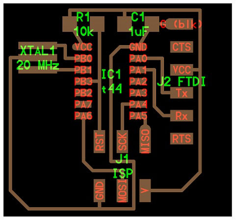
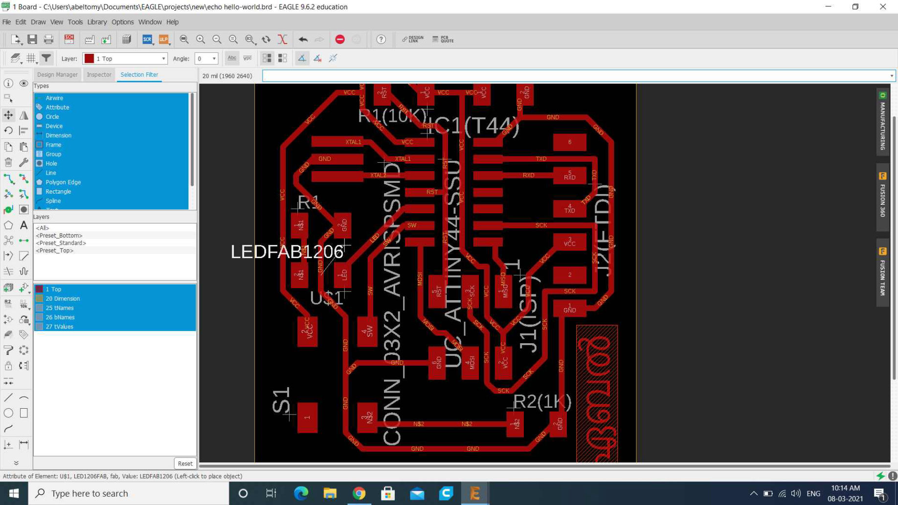
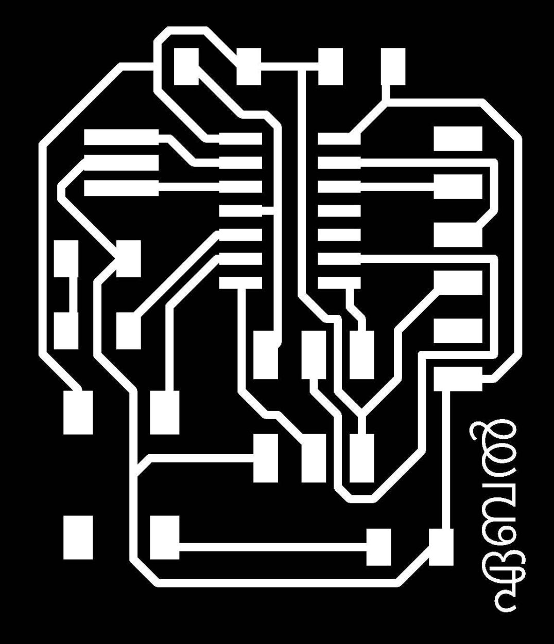
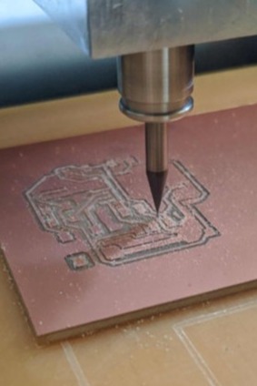
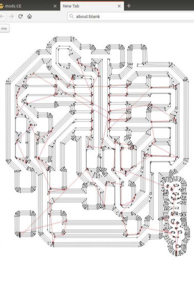
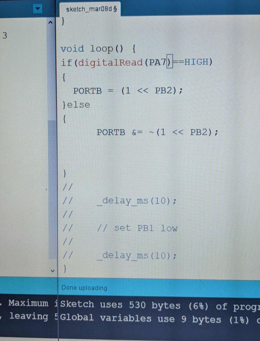
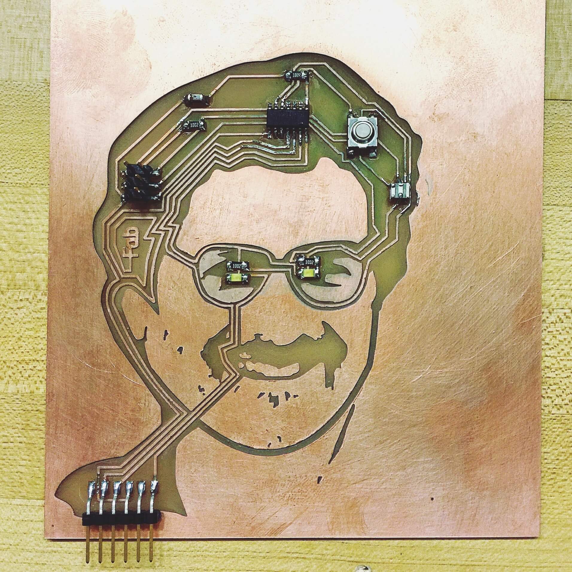
The Assignment was to add a LED and a switch at lest to the circuit.First i drew the basic Echo-board and next i additionally added an LED and Push Button, on the PCB
COMPONENTS
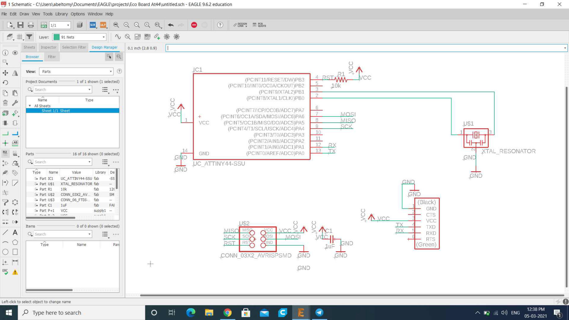
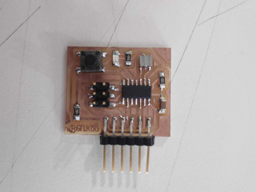
ATtiny44 x 1 - This is a programmable micro controller chip that controls all the parts on the board and is programmed from the computer. Let us say this is the brain of our Board.
XTAL 20HZ x 1 - This Resonance crystal acts as an external clock for the circuit. It needs the input traces to be connected to two pins on the board and the ground trace to the GND circuit.
Resistor 10K x 2
Resistor 99ohm x 1
Capacitor 10uf x 1 - this is a device used to store electric charge, consisting of one or more pairs of conductors separated by an insulator. This will help filter devices to remove voltage or signal spikes in our circuit.
Push button x 1
ISP header x 1 - the 2x3 pin header that connects the FabISP to our newly created chip(ISP - In System Programmer, I have alreay made a FabISP (In System Programmer) board, as part of completing an earlier week’s assignment)
FTDI header x1 -the 1x6 pin header that connects to the special FTDI USB cable (FTDI is Future Technology Devices International - The company that makes a special usb cable - and drivers that let us write to the 6 pin output like a standard serial port.)This will connect the circuit to the computer to both read the program and power the board. It’s VCC and GND pins need to be connected to the respective VCC and GND circuits on the board, and it’s Tx and Rx pins connect to the two free pins on the microcontroller.

Mobirise

Adding Library

Designing Schematic Diagram

1.I have installed the fab library from this.
2.In Eagle, I have created a new project, by clicking File => New => Project and named it, then created a new schematic by clicking File => New => Schematic
 3.In the command line (just below the menus at the top), type add.
4.Since we added the fab library to this path already, we expect that EAGLE will find it. They are in alphabetical order, so I scrolled down to find the fab library and clicked the triangle next to it to see the list of contents in it.
5. Left click to place the component in the schematic.
Place this part in the center of your schematic. Press escape to return to the add menu, and then escape to exit the ‘add’ tool.
6.Similarly add all other components.


Mobirise

Once all components are added the screen looks like this.

Mobirise

Setting Design Rules

Designing PCB

From the file menu take Switch to Board Button and press it.
Set Design Rules
 Change the design rules by clicking on the Design Rules button under Edit Menu Here are the changes I made in accordance with our lab equipment's.
The bit we use here in Superfablab, Kochi for milling is 1/64 bit. So here the trace will come around 16 mil.

All clearance measurements have been changed from the default 6mil to 16 mil.

Mobirise

Start drag and drop the electronics components on the board to black area. Organize the layout of the components, rotate them and keep what is connected to each other next to each other to make the routing easier later on.
Once components are more or less aligned and as close to their corresponding connections, the traces has to be made using the traces tool. Click on the center of a component to start a trace, then right-click to change angles.
Routing
I used Auto route by pressing the tool Autorouter from the toolbox.
Autoroute will suggest many routes, we can choose one that is suitable to us. 
I gave “END JOB’ and removed all the routes by pressing “ripup;” on the command line. Then all the Yellow Lines were revealed like before.
 I started connecting each component manually using Route air wire tool. Once I was satisfied with the connections I gave, I tried to optimize it again. This time I got 85% as the best route.
 I went back to schematic and changed some pins. all changes are reflected on the board diagram.

Mobirise

Final optimized route (i Also Added My name in Malayalam)

Mobirise

Monochrome Exported png trace file

Exporting a board design

Settings should be Monochrome and 1000 DPI - this will export an image with white traces.
The color mode was set to grey scale Image ==> mode ==> grey scale
In the menu, I took View and used the layer settings  and made the top layer visible and hid all other layers.
Also i exported monochrome edition of border by just only enabling border option and increasing border thickness.

Mobirise

FAbmods

Milling

This method was exactly like how we did in PElectronics Production week. I took Mods interface to connect with the Roland Modela MDX-20 to mill. I chose 1/64 bit to trace on the board

Mobirise

Milling

Mobirise

toolpath for Tracing

Mobirise

taaadddda

Soldering

While soldering I placed the ATtiny84 first.I placed a bit of soldering lead on all the pads at first, then started soldering each component in its place.Before programming the board, I checked that there were no shorts with the multimeter. The multi-meter will save a lot of time going crazy debugging if we are certain that our circuit is not working as it is supposed to

Mobirise

yaaee!!!! its workingg.

Mobirise

My Batchmate Shaheen helped me to flash it by fabISP since he is the Powli in Electronics

Mobirise

Multimeter Fluke101

Group Assignment

Multimeter Fluke101
The multimeter we use in our lab is Fluke 101. To restart the multimeter, turn the rotary switch back to the OFF position and then to a necessary position.
Checking for continuity

Turn the dial to resistance (Ω) mode, Push the YELLOW button once to activate the continuity mode.
With the test probes separated, the multimeter’s display will show OL.
Connect the test leads across the component being tested. It is best to connect the VCC connections and ground connections first, and then the connections to each pin on the micro-controller.
The digital multimeter beeps if a complete path (continuity) is detected. If the circuit is open (the switch is in the OFF position), the Multimeter will not beep.

Mobirise

Unisource DS-1100 100 MHz 2 channel digital storage oscilloscope

Unisource DS-1100 100 MHz 2 channel digital storage oscilloscope
A digital oscilloscope is a complex electronic device composed of various software and electronic hardware modules that work together to capture, process, display and store data that represents the signals of interest of an operator.
The resulting digital representations are then stored in a digital memory.(google)


Download design Files.Click here.


Copyright © 2021 Abel's FAB Student agreement .All rights reserved

Built with Mobirise website themes